Home » Without Label » 2014 Yamaha 150 Hp Trim Wiring Diagram / 2014 Yamaha 150 Hp Trim Wiring Diagram : Mercruiser Trim ... - Your trim position sensor (if original) is a wire wound resistor and a wiper arm (rheostat) and the gauge is a voltmeter reading the voltage drop across the resistor.
2014 Yamaha 150 Hp Trim Wiring Diagram / 2014 Yamaha 150 Hp Trim Wiring Diagram : Mercruiser Trim ... - Your trim position sensor (if original) is a wire wound resistor and a wiper arm (rheostat) and the gauge is a voltmeter reading the voltage drop across the resistor.
2014 Yamaha 150 Hp Trim Wiring Diagram / 2014 Yamaha 150 Hp Trim Wiring Diagram : Mercruiser Trim ... - Your trim position sensor (if original) is a wire wound resistor and a wiper arm (rheostat) and the gauge is a voltmeter reading the voltage drop across the resistor.. 170 election road suite 100 draper, ut 84020 phone intl_phone (outside the u.s.a) info@iboats.com This switch permits only a limited amount of outward trim travel to provide safe control at high speeds and prevent damage to drive unit or trim cylinder due to lost side support of drive unit. Click on the image to enlarge, and then save it to your computer by right clicking on the image. View parts diagrams and shop online for v150tlry : Question from a fellow boater.
I bought a faria gauge to match the other farias on my console. Offering discount prices on oem parts for over 50 years. I connected the tach and it works fine. Wiring diagram includes numerous in depth illustrations that display the relationship of assorted things. Here at boats.net, we carry all the parts for your yamaha 150 hp outboard motor!
Trim & Tilt for Sale / Page #31 of / Find or Sell Auto parts from www.2040-parts.com View parts diagrams and shop online for f150xa : Page 2 zmu01690 read this owner's manual carefully before operating your outboard motor.; Wiring diagram includes numerous in depth illustrations that display the relationship of assorted things. Outboard & boat engine wiring colors. 7 pin harnesses do not contain the wires for power trim and tilt. A wiring diagram is a streamlined traditional photographic depiction of an electric circuit. It shows the parts of the circuit as streamlined shapes, as well as the power and also signal connections in between the tools. A new style one works the same way, except the resistor material is deposited on a plastic sheet, and the contact moves.
Here is a listing of common color codes for yamaha outboard motors.
A new style one works the same way, except the resistor material is deposited on a plastic sheet, and the contact moves. The main harness is used to connect the engine to the electrical part of conventional controls. Click on the image to enlarge, and then save it to your computer by right clicking on the image. The use of a schematic diagram solves this problem. Collection of yamaha outboard tachometer wiring diagram. I was hoping a factory rep could confirm that the connector and connector location shown in the pictures in this post is the correct connector for this gauge/cable. I assume the wiring harness was for the original engine. Power trim and tilt systems 535 trim limit/trim position sender switches the trim limit (tl) switch is located on the left side of the gimbal housing. Digital trim connection if the yamaha engine was previously connected to an analog trim gauge, the trim information output by the engine onto the nmea 2000 network will be inaccurate. Vessels nmea2000 network as shown in the system diagram on page 1 of this document. I connected the tach and it works fine. This switch permits only a limited amount of outward trim travel to provide safe control at high speeds and prevent damage to drive unit or trim cylinder due to lost side support of drive unit. View parts diagrams and shop online for v150tlry :
Wiring diagram includes numerous in depth illustrations that display the relationship of assorted things. In electrical wiring the term lavender is not used as a wire insulation color. I was hoping a factory rep could confirm that the connector and connector location shown in the pictures in this post is the correct connector for this gauge/cable. Question from a fellow boater. Page 2 zmu01690 read this owner's manual carefully before operating your outboard motor.;
Mercury Outboard Tachometer Wiring - Wiring Diagram from lh3.googleusercontent.com Collection of yamaha outboard wiring diagram pdf. Outboard & boat engine wiring colors. View parts diagrams and shop online for f150xa : Sw3 oil warning red light v4. Yamaha outboard wiring diagram inspirational yamaha 703 remote. I connected the tach and it works fine. This allows easier interchanging of yamaha outboards with the same classification because the mounting dimensions are the same. 170 election road suite 100 draper, ut 84020 phone intl_phone (outside the u.s.a) info@iboats.com
I later upgraded to a 2006 50 hp 2 stroke w ptt.
Boat manual boat motor manuals repair boat manuals with service and repair information all boat motor manuals contain wiring diagrams step by step instructions and hundreds of photos to help. Important manual information emu31280 your machine and this manual. Tilt and trim switch wiring diagram beautiful 1978 johnson outboard 1991 johnson 25 hp wiring. The use of a schematic diagram solves this problem. Collection of yamaha outboard wiring diagram pdf. It shows the parts of the circuit as streamlined shapes, as well as the power and also signal connections in between the tools. We are your trusted online solution when it comes time for your next catalog lookup regarding yamaha outboard parts and diagrams. Digital trim connection if the yamaha engine was previously connected to an analog trim gauge, the trim information output by the engine onto the nmea 2000 network will be inaccurate. Page 2 zmu01690 read this owner's manual carefully before operating your outboard motor.; Vessels nmea2000 network as shown in the system diagram on page 1 of this document. Offering discount prices on oem parts for over 50 years. Why do boater's shop for yamaha outboard repair parts at ppt? The dealer explained the gauge and cable wiring color codes to me so i think i'm ok there.
Why do boater's shop for yamaha outboard repair parts at ppt? I later upgraded to a 2006 50 hp 2 stroke w ptt. Boat manual boat motor manuals repair boat manuals with service and repair information all boat motor manuals contain wiring diagrams step by step instructions and hundreds of photos to help. Here is a listing of common color codes for yamaha outboard motors. Most maintenance and repairs can be handled with ease without even leaving the house.
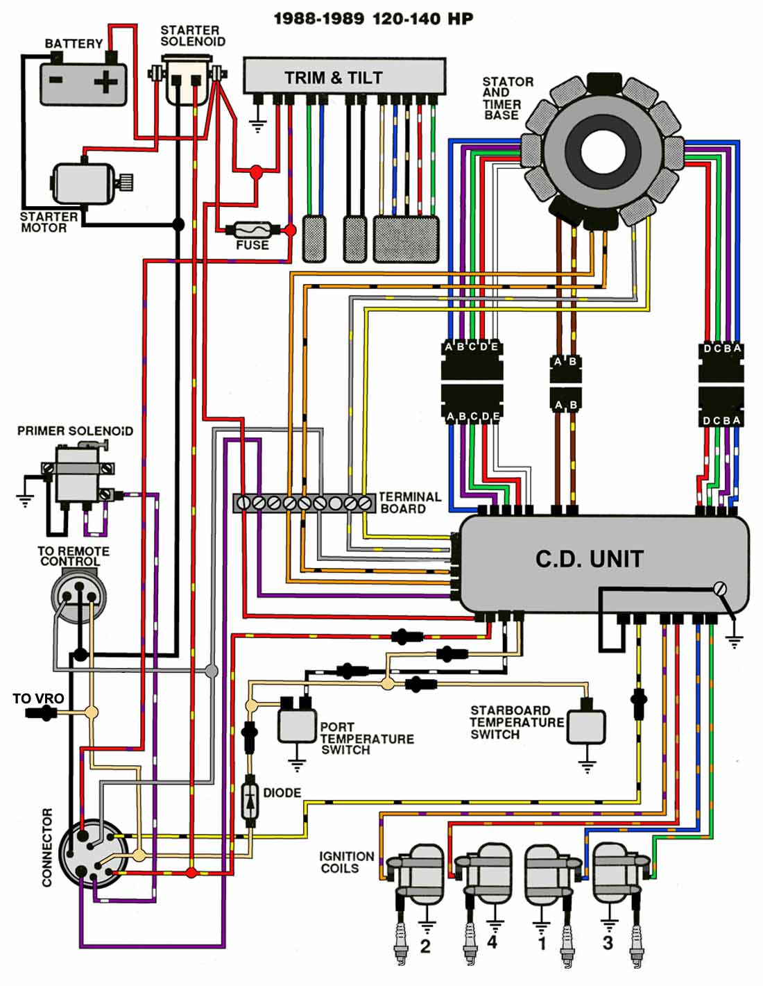
Mastertech Marine -- EVINRUDE JOHNSON Outboard Wiring Diagrams from maxrules.com Cooling system features and benefits cooling system the cooling water flow diagram is as. Your trim position sensor (if original) is a wire wound resistor and a wiper arm (rheostat) and the gauge is a voltmeter reading the voltage drop across the resistor. 1973 140 hp mercruiser trim goes down but not up replaced motor solenoid works when i hook blue wire direct to. Digital trim connection if the yamaha engine was previously connected to an analog trim gauge, the trim information output by the engine onto the nmea 2000 network will be inaccurate. Dl 3827 mercruiser tilt trim wiring diagram on 3 wire and schematic. I later upgraded to a 2006 50 hp 2 stroke w ptt. 2008 yamaha 50 2 stroke outboard wiring manual. A wiring diagram is a streamlined traditional photographic depiction of an electric circuit.
The dealer explained the gauge and cable wiring color codes to me so i think i'm ok there.
Volvo penta exploded view schematic power trim system tsk sx c1 c1ac r1 r2 marinepartseurope com. On my yamaha fb115, i found the trim sending unit on the motor itself, with the wiring going somewhere. Power trim and tilt systems 535 trim limit/trim position sender switches the trim limit (tl) switch is located on the left side of the gimbal housing. Here is a listing of common color codes for yamaha outboard motors. Yamaha 200 outboard wiring diagram 2007 diagrams news road 2000 t50 marine full version hd quality outletdiagram politopendays it starter switch post outgive trim sensor mayor oil tank 1998 installation core parafarmacialofaro 30 hp long seat 2003 90 2 stroke please help the hull truth boating and fishing forum johnson 50 free picture 2018 f150 fuse box begeboy… read more » 1979 70 hp mercury outboard tach wiring diagram circuit diagram. The main harness is used to connect the engine to the electrical part of conventional controls. I was hoping a factory rep could confirm that the connector and connector location shown in the pictures in this post is the correct connector for this gauge/cable. View parts diagrams and shop online for f150xa : Sw3 oil warning red light v4. Collection of yamaha outboard wiring diagram pdf. A new style one works the same way, except the resistor material is deposited on a plastic sheet, and the contact moves. Question from a fellow boater.